


LCD 使用
更新时间:2018-03-15 阅读:13526
简介
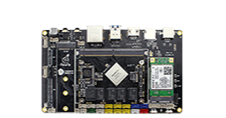
AIO-3399J开发板外置了两个LCD屏接口,一个是EDP,一个是LVDS,接口对应板子上的位置如下图:
Config配置
以Android7.1为例,AIO-3399J默认的配置文件kernel/arch/arm64/configs/firefly_defconfig已经把LCD相关的配置设置好了,如果自己做了修改,请注意把以下配置加上:
CONFIG_LCD_MIPI=y
CONFIG_MIPI_DSI=y
CONFIG_RK32_MIPI_DSI=y
DTS配置
引脚配置
LVDS屏
AIO-3399J的SDK有LVDS DSI的DTS文件:kernel/arch/arm64/boot/dts/rockchip/rk3399-firefly-aio-lvds.dts,从该文件中我们可以看到以下语句:
/ {
    model = "AIO Board lvds (Android)";
    compatible = "rockchip,android", "rockchip,rk3399-firefly-lvds", "rockchip,rk3399";

    test-power {
        status = "okay";
    };

```

&dsi {
    status = "okay";
    dsi_panel: panel {
        compatible ="simple-panel-dsi";
        reg = ;
        //ddc-i2c-bu
        //power-supply = ;
        //pinctrl-0 = ;
        backlight = ;
        /*
        enable-gpios = ;
        reset-gpios = ;
        */
        dsi,flags = ;
        dsi,format = ;
        //bus-format = ;
        dsi,lanes = ;

        dsi,channel = ;

        enable-delay-ms = ;
        prepare-delay-ms = ;

        unprepare-delay-ms = ;
        disable-delay-ms = ;

        size,width = ;
        size,height = ;

        status = "okay";
...
        power_ctr: power_ctr {
               rockchip,debug = ;
               lcd_pwr_en: lcd-pwr-en {
                       gpios = ;
                       pinctrl-names = "default";
                       pinctrl-0 = ;
                       rockchip,delay = ;
               };

               lcd_rst: lcd-rst {
                       gpios = ;
                       pinctrl-names = "default";
                       pinctrl-0 = ;
                       rockchip,delay = ;
               };
           };
...
&pinctrl {
    lcd-panel {
        lcd_panel_reset: lcd-panel-reset {
            rockchip,pins = ;
        };

        lcd_panel_pwr_en: lcd-panel-pwr-en {
            rockchip,pins = ;
        };

    };
这里定义了LCD的电源控制引脚:
lcd_pwr_en:(GPIO3_C0)GPIO_ACTIVE_HIGH
lcd_rst:(GPIO2_D3)GPIO_ACTIVE_HIGH
都是高电平有效,具体的引脚配置请参考《GPIO》一节。
配置背光
AIO-3399J开发板外置了一个背光接口用来控制屏幕背光,如下图所示:

在DTS文件:kernel/arch/arm64/boot/dts/rockchip/rk3399-firefly-core.dtsi中配置了背光信息,如下:
/ {
    compatible = "rockchip,rk3399-firefly-core", "rockchip,rk3399";

    backlight: backlight {
        status = "disabled";
        compatible = "pwm-backlight";
        pwms = ;
        brightness-levels = ;
        default-brightness-level = ;
    };
pwms属性:配置PWM,范例里面默认使用pwm0,25000ns是周期(40 KHz)。LVDS需要加背光电源控制脚,在kernel/arch/arm64/boot/dts/rockchip/rk3399-firefly-aio-lvds.dts中可以看到以下语句:
&backlight {
    status = "okay";
    enable-gpios = ;
    brightness-levels = ;
};
因此使用时需修改DTS文件。
brightness-levels属性:配置背光亮度数组,最大值为255,配置暗区和亮区,并把亮区数组做255的比例调节。比如范例中暗区是255-221,亮区是220-0。
default-brightness-level属性:开机时默认背光亮度,范围为0-255。
具体请参考kernel中的说明文档:kernel/Documentation/devicetree/bindings/leds/backlight/pwm-backlight.txt
配置显示时序
LVDS屏
与EDP屏不同,LVDS屏的 Timing 写在DTS文件中,在kernel/arch/arm64/boot/dts/rockchip/rk3399-firefly-aio-lvds.dts中可以看到以下语句:
disp_timings: display-timings {
    native-mode = ;
    timing0: timing0 {
         clock-frequency = ;
         hactive = ;
         vactive = ;
         hsync-len = ;   //20, 50
         hback-porch = ; //50, 56
         hfront-porch = ;//50, 30
         vsync-len = ;
         vback-porch = ;
         vfront-porch = ;
         hsync-active = ;
         vsync-active = ;
         de-active = ;
         pixelclk-active = ;
           };
    }
}
时序属性参考下图:
Init Code
LVDS屏
lvds屏上完电后需要发送初始化指令才能使之工作。
Dts
可以在kernel/arch/arm64/boot/dts/rockchip/rk3399-firefly-aio-lvds.dts中可以看到lvds的初始化指令列表:
&dsi {
            status = "okay";

        ```
        panel-init-sequence = [
    29 00 06 3C 01 09 00 07 00
    29 00 06 14 01 06 00 00 00
    29 00 06 64 01 0B 00 00 00
    29 00 06 68 01 0B 00 00 00
    29 00 06 6C 01 0B 00 00 00
    29 00 06 70 01 0B 00 00 00
    29 00 06 34 01 1F 00 00 00
    29 00 06 10 02 1F 00 00 00
    29 00 06 04 01 01 00 00 00
    29 00 06 04 02 01 00 00 00
    29 00 06 50 04 20 01 F0 03
    29 00 06 54 04 32 00 B4 00
    29 00 06 58 04 80 07 48 00
    29 00 06 5C 04 0A 00 19 00
    29 00 06 60 04 38 04 0A 00
    29 00 06 64 04 01 00 00 00
    29 01 06 A0 04 06 80 44 00
    29 00 06 A0 04 06 80 04 00
    29 00 06 04 05 04 00 00 00
    29 00 06 80 04 00 01 02 03
    29 00 06 84 04 04 07 05 08
    29 00 06 88 04 09 0A 0E 0F
    29 00 06 8C 04 0B 0C 0D 10
    29 00 06 90 04 16 17 11 12
    29 00 06 94 04 13 14 15 1B
    29 00 06 98 04 18 19 1A 06
    29 02 06 9C 04 33 04 00 00
        ];

        panel-exit-sequence = [
            05 05 01 28
            05 78 01 10
        ];
        ```
        };
命令格式以及说明可参考以下附件:
![]() Rockchip DRM Panel Porting Guide.pdf
Rockchip DRM Panel Porting Guide.pdf
kernel
发送指令可以看到在kernel/drivers/gpu/drm/panel/panel-simple.c文件中的操作:
    static int panel_simple_enable(struct drm_panel *panel)
{
    struct panel_simple *p = to_panel_simple(panel);
    int err;
    if (p->enabled)
        return 0;
    DBG("enter\n");
    if (p->on_cmds) {
        err = panel_simple_dsi_send_cmds(p, p->on_cmds);
        if (err)
            dev_err(p->dev, "failed to send on cmds\n");
    }
    if (p->desc && p->desc->delay.enable) {
        DBG("p->desc->delay.enable=%d\n", p->desc->delay.enable);
        msleep(p->desc->delay.enable);
    }
    if (p->backlight) {
        DBG("open backlight\n");
        p->backlight->props.power = FB_BLANK_UNBLANK;
        backlight_update_status(p->backlight);
    }
    p->enabled = true;
    return 0;
}
U-boot
The sending instruction can see the operation in the u-boot/drivers/video/rockchip-dw-mipi-dsi.c:
static int rockchip_dw_mipi_dsi_enable(struct display_state *state)
{
    struct connector_state *conn_state = &state->conn_state;
    struct crtc_state *crtc_state = &state->crtc_state;
    const struct rockchip_connector *connector = conn_state->connector;
    const struct dw_mipi_dsi_plat_data *pdata = connector->data;
    struct dw_mipi_dsi *dsi = conn_state->private;
    u32 val;
    DBG("enter\n");
    dw_mipi_dsi_set_mode(dsi, DW_MIPI_DSI_VID_MODE);
    dsi_write(dsi, DSI_MODE_CFG, ENABLE_CMD_MODE);
    dw_mipi_dsi_set_mode(dsi, DW_MIPI_DSI_VID_MODE);
    if (!pdata->has_vop_sel)
        return 0;
    if (pdata->grf_switch_reg) {
        if (crtc_state->crtc_id)
            val = pdata->dsi0_en_bit | (pdata->dsi0_en_bit dsi0_en_bit grf_switch_reg);
    }
    debug("vop %s output to dsi0\n", (crtc_state->crtc_id) ? "LIT" : "BIG");
    //rockchip_dw_mipi_dsi_read_allregs(dsi);
    return 0;
}